


On a BT Smart module external switches can be connected to the GPIO ports in order to control real time transmitter tasks through events. Transmitter events are triggers that allow to execute various tasks you may specify, such as announcing an individual value or a value list, controlling application navigation or switching the vario sound player on and off. If you you own an iMSB BT Smart data module you can connect up to eight on/off or momentary switches to the module’s GPIO ports. Note that this functionality is available for the iMSB for M-Link, iMSB for FrSky and iMSB for HoTT application versions.
Your iMSB BT Smart module disposes of eight GPIO ports, identified as GPIO 0 to GPIO 7 on the back of the module. Each switch needs to be connected between the GND pin and a dedicated GPIO pin, as shown in the picture below.

Before you can use your GPIO switches the iMSB BT Smart module must however be configured beforehand in the iMSB app, as described here:
- Open the “Application settings” and go to “Data module setup”
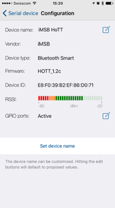
- When your module is shown on the screen select its details
- In the device configuration view the last entry shows a line “GPIO ports”. Its status should be inactive for now
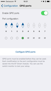
- Select the edit button on the “GPIO ports” line. This will show the GPIO configuration screen
- Make sure that the “Enable GPIO ports” switch is enabled
- Each port can be configured as normal, inverted or disabled. Please make sure that the port on which a switch is connected is in normal or inverted state. You may additionally check the switch function on the same screen
- Finally hit the “Configure GPIO ports” button. This will store permanently your configuration in the module