The information on this page is intended for users wishing to build their own module instead of purchasing one directly from iMSB.
As the iPhone does not have a usable serial interface and does not support serial Bluetooth converters, the best method (although not the cheapest) at the time being is to transfer telemetry data via TCP/IP over a WiFi network. Hence a serial to Wi-Fi module is needed to perform this task.
Although any suitable product available on the market can be used for this task, I recommend devices based on Microchip RN-171 or RN-131 802.11 b/g embedded UART to TCP/IP modules. The two main reasons for this recommendation are that iMSB has yet only been tested with these products and that the application can take care of configuring these modules automatically for you.
Microchip proposes a wide range of products that are more or less easy to interface with Multiplex® transmitters. The following modules have been tested and are supported by iMSB:
• RN-174
• RN-131
• RN-XV
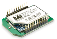
Among these we recommend using the RN-XV as it has one of the smallest footprint and is currently the cheapest solution available. Additionally it is perfectly suited for iMSB’s tasks.
This module can be powered directly from the M-Link HF transmitter COM port (3.3 V compatible) and does thus not require any additional voltage regulation. In its basic form interfacing can be done quite easily. Positive voltage and ground need to be connected to the corresponding module pins (pin 1 and pin 10 respectively) and the signal line is connected to the RN-XV Uart RX pin (pin 3) via a 12K pull-down resistor. Although this is well suited for test purposes, we do however recommend properly interfacing the module according to the guidelines described below.
Hardware Interfacing
The interface description provided in this section is specifically intended for Microchip's RN-XV serial to Wi-Fi device. The interfacing principles remain however valid for any other module you may choose, except that the pin layout needs eventually to be adapted accordingly.
The Multiplex® HF module COM port is laid out as half-duplex 1-wire bus operated at 3.3V TTL level, which needs to be interfaced with the RN-XV UART 2-wire RX and TX ports. Fortunately both sides operate at the same voltage level, such as additional regulation is not required, which will keep the interface complexity to a strict minimum.
The proposed interface diagram is shown in the picture below:
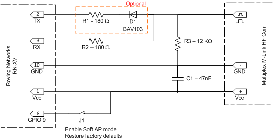
Communication between the 1-wire Com port side and the Wifly UART can be performed via a very simple open-drain bus master interface, realised through components R1, R2 and D1. However as the current M-Link implementation only sends information to the telemetry data consumer, the connection to the TX data line (pin 2) via D1 and R1 can be safely omitted, thus leaving TX floating.
The R3 pull-down resistor is required to insure that the input is pulled down to a logic low. Omitting the resistor prevents the HF-module to communicate safely with the model receiver.
When configuring the Wi-Fi device for the first time or after a factory reset, the module needs to be forced into soft AP mode (the factory default being set to infrastructure mode). This must be achieved by driving GPIO 9 (pin 8) to high while the module boots. Jumper J1 realises this by simply connecting GPIO 9 to the Vcc line.
Note that any unused RN-XV port can be simply left unconnected.
For additional electrical and configuration details please refer to the RN-XV user manual available on the manufacturer’s web site.
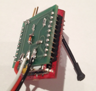
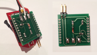
The physical realisation of the interface can be quite easily performed by soldering the required discreet components and access wires directly on the RN-XV headers. A safer and more professional approach would be to realise a small PCB holding all necessary components. The PCB can then be soldered directly to the RN-XV through hole headers.
Once the electrical interface is realised you will need to configure the Wi-Fi module for proper operation with iMSB.